3D planning with SolidWorks Routing.

SolidWorks Routing
01.02.2017

So that problems can be recognized already at the planning stage, and not only when the unit is installed.

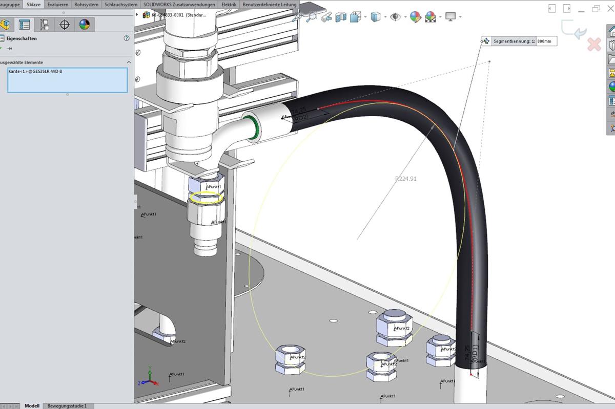
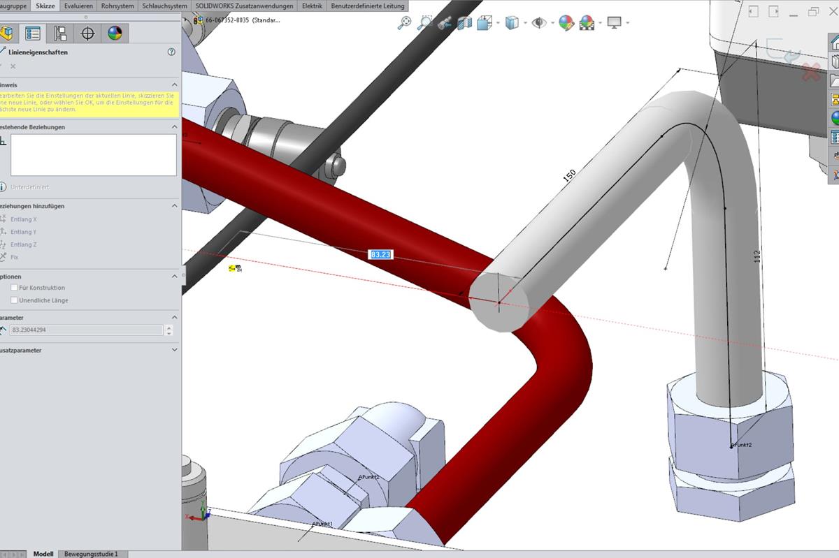
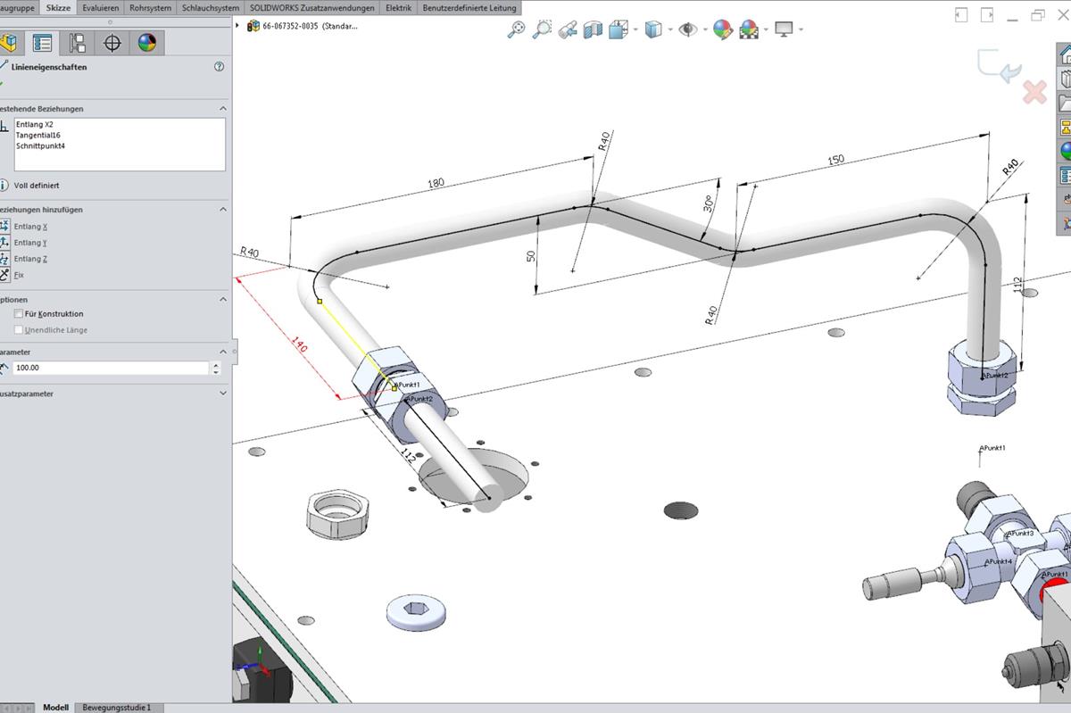
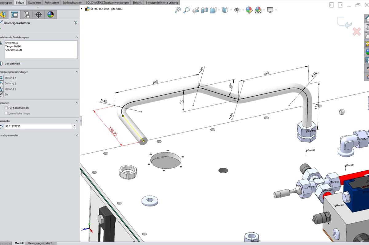
By preplanning pipes, hoses and electric wiring in 3D, the customer now receives an exact model of their hydraulic unit or control system with all necessary connections and pipework.

SolidWorks is a 3D CAD program from the Dassault Systèmes SolidWorks Corp. software company that is used in machine building among other areas for the planning of production parts. The Routing module is a special module that is only included in the most comprehensive “SolidWorks Premium” license. Whereas in the past preplanning was either rare or was not done, unit builders can profit today from the possibility of early recognition and the highest level of flexibility in 3D planning with SolidWorks Routing.

The process

The routing usually begins when all other components for a unit (accumulators, control systems, pump station, etc.) have been linked in the 3D assembly. Then all connections are inserted at the appropriate positions in accordance with the wiring diagram, along with all threads, T fittings, cross fittings and, where hoses are used, hose fittings. Afterwards, two pipe connections belonging together are connected with the Routing module. In the process, for every connector size the appropriate geometry is saved in the 3D model (piping diameter, wall thickness, bending radius, minimum side length for WALFORM process). The piping route can then be automatically calculated, i.e. the guide line (=3D sketch line) is automatically suggested by the program. There are always multiple suggestions available. For complicated pipe routing, the guide line can also be drawn with manually drawn sketch lines (e.g. for levels with angle information).

For hose lines, the routing also works with a 3D sketch line, but with an automatically or manually drawn spline, as hoses do not run straight. All geometries and minimum bending curves are also stored in the 3D models for hoses. In this way, all piping connections are connected with each other.

When the unit has been released by the customer, dimensioned 2D drawings are produced of all pipes, which saves the assembler in production from measuring the pipe connectors. He/she can start with the pipe bending work immediately on the basis of the pipe drawings.

Why it makes sense to plan piping in 3D:

Our customers can exactly check this model for whether their machine frame or the installation space envisaged is sufficient. They can even have individual pipes changed if they want a different routing. Problems that would only arise during installation of the unit in the plant without complete pipe planning can now be recognized in good time in the planning phase and solved. Design errors are reduced and thus also downtime for problems that delay the commissioning at the customer.

  • Compact unit layout for all unit sizes to small units with minimal space requirements
  • Optimized flow configurations in the piping system
  • Maintenance friendly layout
  • Planning for upgrade possibilities
  • Short production and assembly times
  • Check of the minimum bending radii for hoses (resulting in longer lifetimes)
  • Detailed planning in close communication with the customer

YOUR CONTACT PERSON

Oliver Fath

Manager of the technical back office CAD
+49 9208 657439-32
Oliver Fath

Similar topics